SPI decoding on the Raspberry Pi Pico
This was an experiment to decode the SPI data sent from a Pico to a TFT display from Pimoroni, using my recent purchase - the Siglent SDS1104X-E oscilloscope.
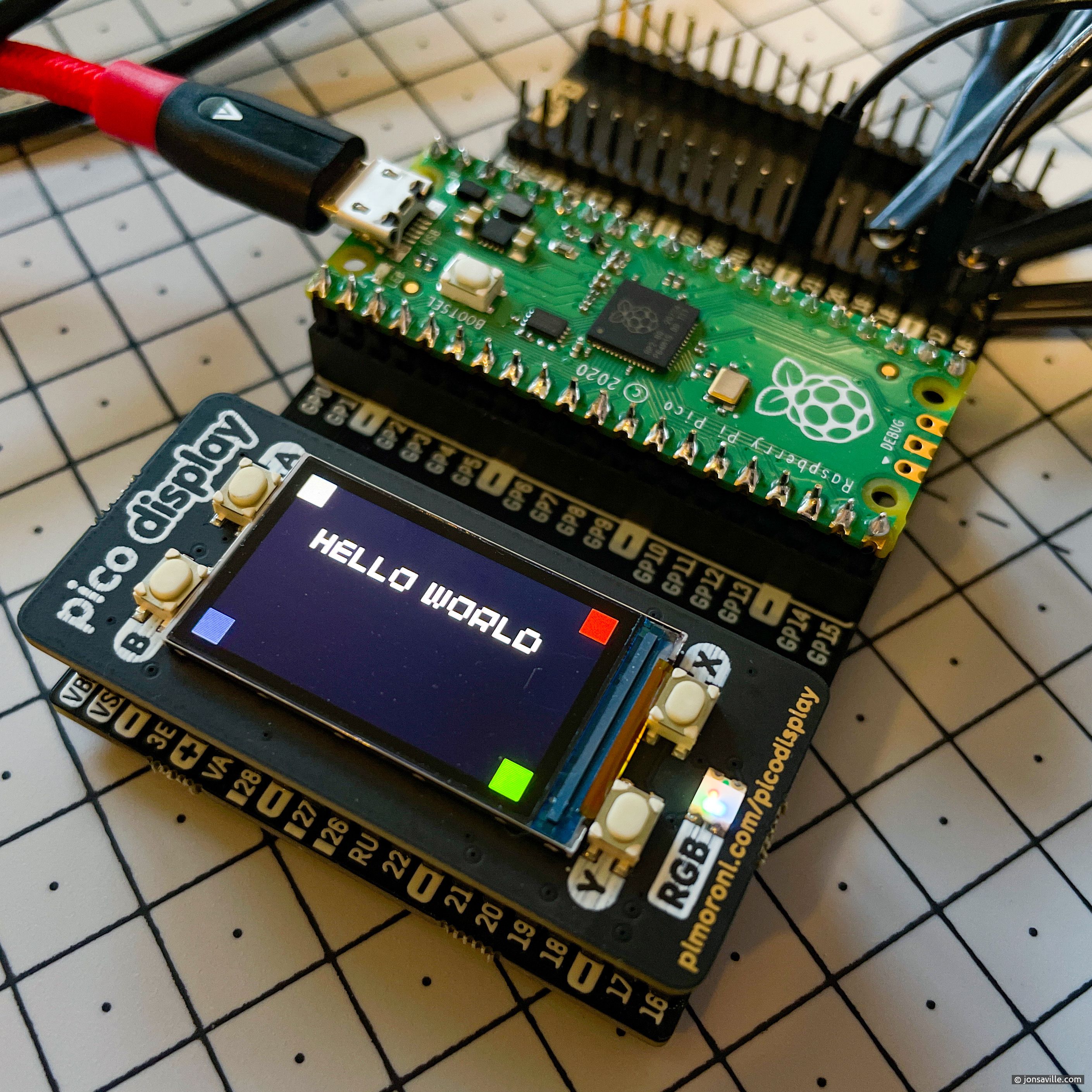
To generate some test data, I modified the sample program supplied with the display to place four blocks of colour in the corners. These colour blocks are rotated every 10 seconds.
I used a Raspberry Pi 4 as the compilation platform. The Pico and Pimoroni’s libraries install without fuss, and very little work was needed to get the sample application compiling with my modifications. I used the Samba library to share the Pi 4 filesystem to my Windows PC - this made it easier to edit the code in MS Visual Code, and to copy the binary to the Pico.
In order to test whether the scope was decoding the SPI data correctly, I needed to determine what it should look like in the first place. The Pimoroni display uses a Sitronix ST7789 display controller, which has a simplex [command][data] control protocol. The Pimoroni driver repurposes the Pico’s SPI MISO line to be an additional output signal for command. The four lines used are:
- Clock (CLK)
- Data out (MOSI)
- Chip select (CS, active low)
- Command assert (DC, active low)
The sequence of signals to send something to the display is therefore:
- Assert CS and DC
- Clock the display command (one byte) out, MSB first
- De-assert DC
- Clock the data out, MSB first
- De-assert CS
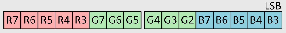
The display’s default pixel bit-depth is 16 bits. RGB values are packed into two bytes as follows, with the most significant bits being taken from each input byte.
I chose the following colours for the corner blocks (plus white).
| Block colour | Decimal RGB | Packed binary | Packed hex |
|---|---|---|---|
| Red | 255, 10, 20 | 11111000 01000010 | F8 42 |
| Green | 30, 245, 40 | 00011111 10100101 | 1F A5 |
| Blue | 50, 60, 235 | 00110001 11111101 | 31 FD |
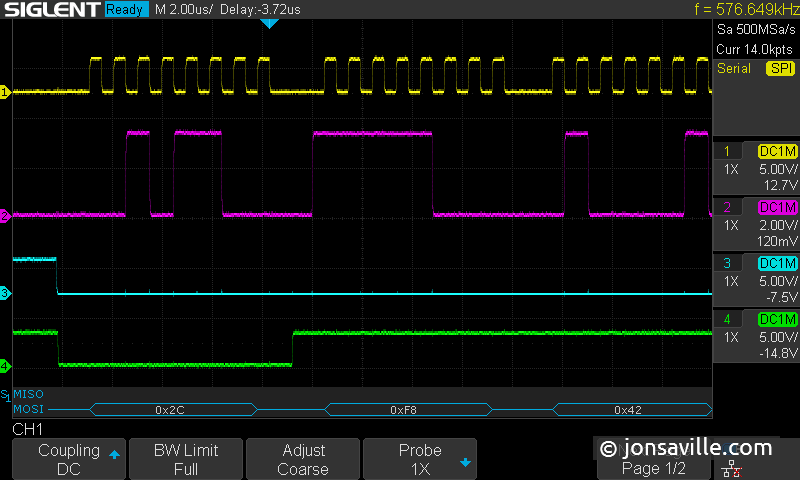
I wasn’t prepared for how fast the SPI can be clocked - the Pimoroni library sets it to 64Mbps. This is beyond the resolution of my scope, so I reduced the data rate to 1Mbps. After a certain amount of fiddling with the serial decoding settings and triggering, I got the trace shown below when the red block was at the origin (0,0) corner. Checking the ST7789 datasheet, 0x2C is the command to write data to its internal memory - in this case, followed by a pixel of “red” colour 0xF842. Success!